Product Description
Product Description
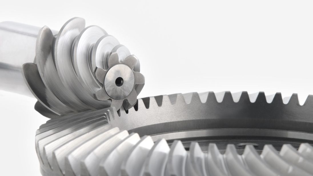
Precision Metal Steel Brass Drive Wheel Transmission Pinion straight bevel Helical Gear
| Item | Customized machined machining gears | |
| Process | CNC machining,CNC milling, cnc lathe machining | |
| material | steel, stainless steel, carbon steel,brass,C360 brass copper, aluminum 7075,7068 brass,C360 brass copper, aluminum Nylon, PA66, NYLON , ABS, PP,PC,PE,POM,PVC,PU,TPR,TPE,TPU,PA,PET,HDPE,PMMA etc | |
| Quality Control | ISO9001 and ISO14001 | |
| Dimension bore tolerances | -/+0.01mm | |
| Quality standard | AGMA, JIS, DIN | |
| Surface treatment | Blackening, plated, anodizing, hard anodizing etc | |
| Gear hardness | 30 to 60 H.R.C | |
| Size/Color | Gears and parts dimensions are according to drawings from customer, and colors are customized | |
| Surface treatment | Polished or matte surface, painting, texture, vacuum aluminizing and can be stamped with logo etc. | |
| Dimensions Tolerance | ±0.01mm or more precise | |
| Samples confirmation and approval | samples shipped for confirmation and shipping cost paid by customers | |
| Package | Inner clear plastic bag/outside carton/wooden pallets/ or any other special package as per customer’s requirements. | |
| Delivery Time | Total takes 2~~8weeks usually | |
| Shipping |
Usual FEDEX, UPS, DHL, TNT, EMS or base on customer’s requirement. |
Production management:
1. The workers are trained to inspect the gears and notice any defect in production in time.
2. QC will check 1pcs every 100pcs in CNC machining, and gears will meet all dimension tolerances.
3. Gears will be inspected at every step, and gears will be inspected before shipment, and all inspection records will be kept in our factory for 3 years.
4. Our sales will send you pictures at every gears production steps, and you will know the detailed production status, and you can notice any possibility of mistake, for our sales, QC and workers are keeping close watch on all production.
5. You will feel us working very carefully to assure the quality and easy to work with,
6. we cherish every inquiry, every opportunity to make gears and parts and cherish every customer.
QUALITY CONTROL PROCESS:
1) Inspecting the raw material –IQC)
2) Checking the details before the production line operated
3) Have full inspection and routing inspection during mass production—In process quality control (IPQC)
4) Checking the gears after production finished—- (FQC)
5) Checking the gears after they are finished—–Outgoing quality control (OQC)
Service:
1. Molds designs as per customers’ gears drawing;
2. Submitting molds drawings to customers to review and confirm before mols production.
3. Providing samples with whole dimensions and cosmetic inspection report, material certification to customers.
4. Providing inspection report of important dimensions and cosmetic in batches parts.
Packing and shipment:
1. Gears are well and carefully packed in PP bags in CTNS, strong enough for express shipping, air shipment or sea shipment.
2. Air shipment, sea shipment or shipment by DHL, UPS, FedEx or TNT are availabe.
3. Trade terms: EXW, FOB HangZhou, or CIF
4. All shippings will be carefully arranged and will reach your places fast and safely.
FAQ
Q1: How to guarantee the Quality of gears and parts?
We are ISO 9001:2008 certified factory and we have the integrated system for industrial parts quality control. We have IQC (incoming quality control),
IPQCS (in process quality control section), FQC (final quality control) and OQC (out-going quality control) to control each process of industrial parts prodution.
Q2: What are the Advantage of your gears and parts?
Our advantage is the competitive and reasonable prices, fast delivery and high quality. Our eployees are responsible-oriented, friendly-oriented,and dilient-oriented.
Our industrial parts products are featured by strict tolerance, smooth finish and long-life performance.
Q3: what are our machining equipments?
Our machining equipments include plasticn injection machinies, CNC milling machines, CNC turning machines, stamping machines, hobbing machines, automatic lathe machines, tapping machines, grinding machines, cutting machines and so on.
Q4: What shipping ways do you use?
Generally, we will use UPS DHL or FEDEX and sea shipping
5: What materials can you process?
For plastic injection gears and parts, the materials are Nylon, PA66, NYLON with 30% glass fibre, ABS, PP,PC,PE,POM,PVC,PU,TPR,TPE,TPU,PA,PET,HDPE,PMMA etc.
For metal and machining gears and parts, the materials are brass, bronze, copper, stainless steel, steel, aluminum, titanium plastic etc.
Q6: How long is the Delivery for Your gears and parts?
Generally , it will take us 15 working days for injection or machining, and we will try to shorten our lead time.
/* January 22, 2571 19:08:37 */!function(){function s(e,r){var a,o={};try{e&&e.split(“,”).forEach(function(e,t){e&&(a=e.match(/(.*?):(.*)$/))&&1
| Application: | Motor, Electric Cars, Machinery, Toy, Agricultural Machinery, Car |
|---|---|
| Hardness: | Hardened Tooth Surface |
| Gear Position: | External Gear |
| Manufacturing Method: | Cut Gear |
| Toothed Portion Shape: | Curved Gear |
| Material: | Stainless Steel |
| Samples: |
US$ 10/Piece
1 Piece(Min.Order) | |
|---|
| Customization: |
Available
| Customized Request |
|---|
Are bevel gears suitable for high-torque applications?
Bevel gears can indeed be suitable for high-torque applications, depending on various factors such as the specific design, material selection, and proper application engineering. Here’s a detailed explanation:
Bevel gears are known for their ability to transmit power between intersecting shafts at different angles. They can handle significant torque loads and are commonly used in applications that require high-torque transmission. However, the suitability of bevel gears for high-torque applications depends on the following factors:
- Design: The design of the bevel gears plays a crucial role in their ability to handle high torque. Factors such as tooth profile, size, and geometry impact the load-carrying capacity and torque transmission capability. Bevel gears with robust and optimized designs, including suitable tooth profiles and adequate tooth engagement, can effectively handle high-torque applications.
- Material Selection: The choice of materials for bevel gears is critical in high-torque applications. Gears need to be made from materials with high strength, hardness, and wear resistance to withstand the forces and stresses involved in transmitting high torque. Common materials used for bevel gears include alloy steels, carburizing steels, and specialty alloys. Material selection should consider the specific torque requirements, operating conditions, and anticipated loads to ensure the gears can handle the desired torque levels.
- Lubrication: Proper lubrication is essential for reducing friction, wear, and heat generation in high-torque bevel gear applications. Adequate lubrication helps maintain a lubricating film between the gear teeth, minimizing metal-to-metal contact and associated losses. The lubricant type, viscosity, and replenishment schedule should be selected based on the torque and operating conditions to ensure effective lubrication and minimize gear wear.
- Gear Size and Ratio: The size of the bevel gears and the gear ratio can influence their torque-handling capability. Larger gears generally have greater tooth strength and load-carrying capacity, making them more suitable for high-torque applications. The gear ratio should also be considered to ensure it is appropriate for the desired torque transmission and to avoid excessive loads on the gears.
- Operating Conditions: The operating conditions, including speed, temperature, and shock loads, must be taken into account when determining the suitability of bevel gears for high-torque applications. Higher speeds and extreme operating temperatures can affect the gear material properties, lubrication performance, and overall gear system efficiency. Proper cooling, temperature control, and gear protection measures should be implemented to maintain reliable performance under high-torque conditions.
By considering these factors and properly engineering the bevel gear system, it is possible to utilize bevel gears in high-torque applications effectively. However, it is crucial to consult with experienced engineers and perform thorough analysis and testing to ensure the gears can handle the specific torque requirements of the application.

How do you calculate the efficiency of a bevel gear?
To calculate the efficiency of a bevel gear, you need to compare the power input to the gear with the power output and account for any losses in the gear system. Here’s a detailed explanation of the calculation process:
The efficiency of a bevel gear can be calculated using the following formula:
Efficiency = (Power output / Power input) x 100%
Here’s a step-by-step breakdown of the calculation:
- Calculate the Power Input: Determine the power input to the bevel gear system. This can be obtained by multiplying the input torque (Tin) by the input angular velocity (ωin), using the formula:
- Calculate the Power Output: Determine the power output from the bevel gear system. This can be obtained by multiplying the output torque (Tout) by the output angular velocity (ωout), using the formula:
- Calculate the Efficiency: Divide the power output by the power input and multiply by 100% to obtain the efficiency:
Power input = Tin x ωin
Power output = Tout x ωout
Efficiency = (Power output / Power input) x 100%
The efficiency of a bevel gear represents the percentage of input power that is effectively transmitted to the output, considering losses due to factors such as friction, gear meshing, and lubrication. It is important to note that the efficiency of a bevel gear system can vary depending on various factors, including gear quality, alignment, lubrication condition, and operating conditions.
When calculating the efficiency, it is crucial to use consistent units for torque and angular velocity. Additionally, it’s important to ensure that the power input and output are measured at the same point in the gear system, typically at the input and output shafts.
Keep in mind that the calculated efficiency is an approximation and may not account for all the losses in the gear system. Factors such as bearing losses, windage losses, and other system-specific losses are not included in this basic efficiency calculation. Actual efficiency can vary based on the specific design and operating conditions of the bevel gear system.
By calculating the efficiency, engineers can evaluate the performance of a bevel gear and make informed decisions regarding gear selection, optimization, and system design.

How do you calculate the gear ratio of a bevel gear?
Calculating the gear ratio of a bevel gear involves determining the ratio between the number of teeth on the driving gear (pinion) and the driven gear (crown gear). Here’s a detailed explanation of how to calculate the gear ratio of a bevel gear:
The gear ratio is determined by the relationship between the number of teeth on the pinion and the crown gear. The gear ratio is defined as the ratio of the number of teeth on the driven gear (crown gear) to the number of teeth on the driving gear (pinion). It can be calculated using the following formula:
Gear Ratio = Number of Teeth on Crown Gear / Number of Teeth on Pinion Gear
For example, let’s consider a bevel gear system with a crown gear that has 40 teeth and a pinion gear with 10 teeth. The gear ratio can be calculated as follows:
Gear Ratio = 40 / 10 = 4
In this example, the gear ratio is 4:1, which means that for every four revolutions of the driving gear (pinion), the driven gear (crown gear) completes one revolution.
It’s important to note that the gear ratio can also be expressed as a decimal or a percentage. For the example above, the gear ratio can be expressed as 4 or 400%.
Calculating the gear ratio is essential for understanding the speed relationship and torque transmission between the driving and driven gears in a bevel gear system. The gear ratio determines the relative rotational speed and torque amplification or reduction between the gears.
It’s worth mentioning that the gear ratio calculation assumes ideal geometries and does not consider factors such as backlash, efficiency losses, or any other system-specific considerations. In practical applications, it’s advisable to consider these factors and consult gear manufacturers or engineers for more accurate calculations and gear selection.
In summary, the gear ratio of a bevel gear is determined by dividing the number of teeth on the crown gear by the number of teeth on the pinion gear. The gear ratio defines the speed and torque relationship between the driving and driven gears in a bevel gear system.


editor by Dream 2024-05-08