Product Description
Customized Manufacturing High Quality Large Module Gear Rack And Matching Pinion Rack Gear
There are many types of gears such as spur gears, helical gears, bevel gears, worm gears, gear rack, etc. These can be broadly classified by looking at the positions of axes such as parallel shafts, intersecting shafts and non-intersecting shafts.
It is necessary to accurately understand the differences among gear types to accomplish necessary force transmission in mechanical designs. Even after choosing the general type, it is important to consider factors such as: dimensions (module, number of teeth, helix angle, face width, etc.), standard of precision grade (ISO, AGMA, DIN), need for teeth grinding and/or heat treating, allowable torque and efficiency, etc.
Spur Gear
Gears having cylindrical pitch surfaces are called cylindrical gears. Spur gears belong to the parallel shaft gear group and are cylindrical gears with a tooth line which is straight and parallel to the shaft. Spur gears are the most widely used gears that can achieve high accuracy with relatively easy production processes. They have the characteristic of having no load in the axial direction (thrust load). The larger of the meshing pair is called the gear and smaller is called the pinion.
Helical Gear
Helical gears are used with parallel shafts similar to spur gears and are cylindrical gears with winding tooth lines. They have better teeth meshing than spur gears and have superior quietness and can transmit higher loads, making them suitable for high speed applications. When using helical gears, they create thrust force in the axial direction, necessitating the use of thrust bearings. Helical gears come with right hand and left hand twist requiring opposite hand gears for a meshing pair.
Gear Rack
Same sized and shaped teeth cut at equal distances along a flat surface or a straight rod is called a gear rack. A gear rack is a cylindrical gear with the radius of the pitch cylinder being infinite. By meshing with a cylindrical gear pinion, it converts rotational motion into linear motion. Gear racks can be broadly divided into straight tooth racks and helical tooth racks, but both have straight tooth lines. By machining the ends of gear racks, it is possible to connect gear racks end to end.
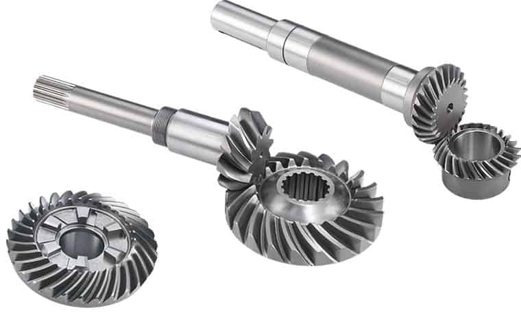
Bevel Gear
Bevel gears have a cone shaped appearance and are used to transmit force between 2 shafts which intersect at 1 point (intersecting shafts). A bevel gear has a cone as its pitch surface and its teeth are cut along the cone. Kinds of bevel gears include straight bevel gears, helical bevel gears, spiral bevel gears, miter gears, angular bevel gears, CHINAMFG gears, zerol bevel gears and hypoid gears.
Screw Gear
Screw gears are a pair of same hand helical gears with the twist angle of 45° on non-parallel, non-intersecting shafts. Because the tooth contact is a point, their load carrying capacity is low and they are not suitable for large power transmission. Since power is transmitted by the sliding of the tooth surfaces, it is necessary to pay attention to lubrication when using screw gears.
Worm Gear
A screw shape cut on a shaft is the worm, the mating gear is the worm wheel, and together on non-intersecting shafts is called a worm gear. Worms and worm wheels are not limited to cylindrical shapes. There is the hour-glass type which can increase the contact ratio, but production becomes more difficult. Due to the sliding contact of the gear surfaces, it is necessary to reduce friction. For this reason, generally a hard material is used for the worm, and a soft material is used for worm wheel. Even though the efficiency is low due to the sliding contact, the rotation is smooth and quiet. When the lead angle of the worm is small, it creates a self-locking feature.
Internal gear
Internal gears have teeth cut on the inside of cylinders or cones and are paired with external gears. The main use of internal gears are for planetary gear drives and gear type shaft couplings. There are limitations in the number of teeth differences between internal and external gears due to involute interference, trochoid interference and trimming problems. The rotational directions of the internal and external gears in mesh are the same while they are opposite when 2 external gears are in mesh.
|
Product name |
Spur Gear & Helical Gear & Gear Shaft |
|
Materials Available |
Stainless Steel, Carbon Steel, Brass, Bronze, Iron, Aluminum Alloy etc |
|
Heat Treatment |
Quenching & Tempering, Carburizing & Quenching, High-frequency Hardening, Carbonitriding…… |
|
Surface Treatment |
Carburizing and Quenching,Tempering ,Tooth suface high quenching Hardening,Tempering |
|
BORE |
Finished bore, Pilot Bore, Special request |
|
Processing Method |
Molding, Shaving, Hobbing, Drilling, Tapping, Reaming, Manual Chamfering, Grinding etc |
|
Pressure Angle |
20 Degree |
|
Hardness |
55- 60HRC |
|
Size |
Customer Drawings & ISO standard |
|
Package |
Wooden Case/Container and pallet, or made-to-order |
|
Certificate |
ISO9001:2008 |
|
Machining Process |
Gear Hobbing, Gear Milling, Gear Shaping, Gear Broaching, Gear Shaving, Gear Grinding and Gear Lapping |
|
Applications |
Toy, Automotive, instrument, electrical equipment, household appliances, furniture, mechanical equipment,daily living equipment, |
|
Advantages |
1. Produce strictly in accordance with ANSI or DIN standard dimension |
Product Process
Application:
About Us:
HangZhou MC Bearing Technology Co.,Ltd (LYMC),who is manufacture located in bearing zone, focus on Slewing bearing, cross roller bearing and pinion,Dia from 50mm-8000mm, Our team with technical and full experience in the bearing industry.
*Professional in researching, developing, producing & marketing high precision bearings for 16 years;
*Many series bearings are on stock; Factory directly provide, most competitive price;
*Advanced CNC equipment, guarantee product accuracy & stability;
*One stop purchasing, product include cross roller bearing, rotary table bearing, robotic bearing, slewing bearing, angular contact ball bearing, large and extra large custom made bearing, diameter from 50~9000mm;
*Excellent pre-sale & after sale service. We can go to customers’ project site if needed.
*Professional technical & exporting team ensure excellent product design, quotation, delivering, documentation & custom clearance.
Our Service:
FAQ:
1.Q: Are you trading company or manufacturer ?
A: We are professional slewing bearing manufacturer with 20 years’ experience.
2.Q: How long is your delivery time?
A: Generally it is 4-5 days if the goods are in stock. or it is 45 days if the goods are not in
stock, Also it is according to quantity.
3.Q: Do you provide samples ? is it free or extra ?
A: Yes, we could offer the sample, it is extra.
4.Q: What is your terms of payment ?
A: Payment=1000USD, 30% T/T in advance, balance before shipment.
5.Q: Can you provide special customization according to the working conditions?
A: Sure, we can design and produce the slewing bearings for different working conditions.
6.Q: How about your guarantee?
A: We provide lifelong after-sales technical service.
/* January 22, 2571 19:08:37 */!function(){function s(e,r){var a,o={};try{e&&e.split(“,”).forEach(function(e,t){e&&(a=e.match(/(.*?):(.*)$/))&&1
| Application: | Motor, Machinery, Marine, Agricultural Machinery, Mining, Petroleum, Automatic,Excavator,Crane, |
|---|---|
| Hardness: | Hardened Tooth Surface |
| Gear Position: | External Gear |
| Toothed Portion Shape: | Helical Bevel Gear |
| Material: | Stainless Steel |
| Type: | Non-Circular Gear |
| Customization: |
Available
| Customized Request |
|---|
How does a bevel gear impact the overall efficiency of a system?
A bevel gear plays a significant role in determining the overall efficiency of a system. Its design, quality, and operating conditions can impact the efficiency of power transmission and the system as a whole. Here’s a detailed explanation of how a bevel gear can impact overall efficiency:
- Power Transmission Efficiency: The primary function of a bevel gear is to transmit power between intersecting shafts at different angles. The efficiency of power transmission through a bevel gear depends on factors such as gear geometry, tooth profile, material quality, lubrication, and operating conditions. In an ideally designed and well-maintained system, bevel gears can achieve high power transmission efficiency, typically above 95%. However, factors such as friction, misalignment, inadequate lubrication, and gear tooth wear can reduce efficiency and result in power losses.
- Friction and Mechanical Losses: Bevel gears experience friction between their mating teeth during operation. This friction generates heat and causes mechanical losses, reducing the overall efficiency of the system. Factors that affect friction and mechanical losses include the gear tooth profile, surface finish, lubrication quality, and operating conditions. High-quality gears with well-designed tooth profiles, proper lubrication, and optimized operating conditions can minimize friction and mechanical losses, improving the overall efficiency.
- Gear Tooth Design: The design of the bevel gear tooth profile influences its efficiency. Factors such as tooth shape, size, pressure angle, and tooth contact pattern affect the load distribution, friction, and efficiency. Proper tooth design, including optimized tooth profiles and contact patterns, help distribute the load evenly and minimize sliding between the teeth. Well-designed bevel gears with accurate tooth profiles can achieve higher efficiency by reducing friction and wear.
- Material Quality and Manufacturing Precision: The material quality and manufacturing precision of bevel gears impact their durability, smooth operation, and efficiency. High-quality materials with suitable hardness, strength, and wear resistance can minimize friction, wear, and power losses. Additionally, precise manufacturing processes ensure accurate gear geometry, tooth engagement, and alignment, optimizing the efficiency of power transmission and reducing losses due to misalignment or backlash.
- Lubrication and Wear: Proper lubrication is crucial for reducing friction, wear, and power losses in bevel gears. Insufficient or degraded lubrication can lead to metal-to-metal contact, increased friction, and accelerated wear, resulting in reduced efficiency. Adequate lubrication with the recommended lubricant type, viscosity, and replenishment schedule ensures a sufficient lubricating film between the gear teeth, minimizing friction and wear and improving overall efficiency.
- Misalignment and Backlash: Misalignment and excessive backlash in bevel gears can negatively impact efficiency. Misalignment causes uneven loading, increased friction, and accelerated wear. Excessive backlash results in power losses during direction changes and can lead to impact loads and vibration. Proper alignment and control of backlash within acceptable limits are crucial for maintaining high efficiency in a bevel gear system.
Overall, a well-designed bevel gear system with high-quality materials, accurate manufacturing, proper lubrication, and minimal losses due to friction, misalignment, or wear can achieve high efficiency in power transmission. Regular maintenance, monitoring, and optimization of operating conditions are essential to preserve the efficiency of the system over time.

What are the potential challenges in designing and manufacturing bevel gears?
Designing and manufacturing bevel gears can present several challenges due to their complex geometry, load requirements, and manufacturing processes. Here’s a detailed explanation of the potential challenges:
When it comes to designing and manufacturing bevel gears, the following challenges may arise:
- Complex Geometry: Bevel gears have intricate geometry with non-parallel and intersecting tooth profiles. Designing bevel gears requires a thorough understanding of gear theory, tooth engagement, and load distribution. The complex geometry poses challenges in determining the optimal tooth profile, tooth contact pattern, and gear ratios for the specific application.
- Load Analysis and Distribution: Determining the correct load analysis and distribution is crucial to ensure the gears can handle the anticipated forces and torques. Bevel gears often encounter varying loads, including radial loads, axial loads, and bending moments. Accurately predicting and distributing these loads across the gear teeth is essential for achieving proper gear strength, minimizing wear, and preventing premature failure.
- Manufacturing Precision: Bevel gears require high manufacturing precision to ensure smooth operation, minimal backlash, and efficient power transmission. Achieving the required precision in gear manufacturing involves precise machining, grinding, and heat treatment processes. The complex geometry of bevel gears adds to the manufacturing complexity, necessitating specialized equipment and skilled operators.
- Alignment Challenges: Proper alignment of bevel gears is critical for optimal performance and longevity. Achieving accurate alignment can be challenging due to the non-parallel shafts and intricate tooth profiles. Misalignment can lead to increased noise, vibration, and premature wear. Design considerations for alignment, as well as careful assembly and alignment procedures during manufacturing, are necessary to address this challenge.
- Lubrication and Cooling: Bevel gears require effective lubrication to minimize friction, wear, and heat generation. Ensuring proper lubrication and cooling can be challenging due to the unique shape of bevel gears and the limited space available for lubricant circulation. Designing appropriate lubrication systems, selecting suitable lubricants, and considering heat dissipation methods are essential for maintaining optimal gear performance and preventing overheating.
- Quality Control: Maintaining consistent quality during the manufacturing process is crucial for reliable bevel gears. Implementing robust quality control measures, including dimensional inspections, surface quality assessments, and gear testing, helps ensure that the manufactured gears meet the specified requirements. Consistency in gear quality is essential to minimize variations in performance and to ensure accurate gear meshing and load distribution.
Addressing these challenges requires a combination of engineering expertise, advanced manufacturing techniques, and quality control processes. Collaborating with experienced gear designers, employing state-of-the-art manufacturing technologies, and conducting thorough testing and analysis can help overcome these challenges and produce high-quality bevel gears that meet the performance and durability requirements of the intended application.

How do you calculate the gear ratio of a bevel gear?
Calculating the gear ratio of a bevel gear involves determining the ratio between the number of teeth on the driving gear (pinion) and the driven gear (crown gear). Here’s a detailed explanation of how to calculate the gear ratio of a bevel gear:
The gear ratio is determined by the relationship between the number of teeth on the pinion and the crown gear. The gear ratio is defined as the ratio of the number of teeth on the driven gear (crown gear) to the number of teeth on the driving gear (pinion). It can be calculated using the following formula:
Gear Ratio = Number of Teeth on Crown Gear / Number of Teeth on Pinion Gear
For example, let’s consider a bevel gear system with a crown gear that has 40 teeth and a pinion gear with 10 teeth. The gear ratio can be calculated as follows:
Gear Ratio = 40 / 10 = 4
In this example, the gear ratio is 4:1, which means that for every four revolutions of the driving gear (pinion), the driven gear (crown gear) completes one revolution.
It’s important to note that the gear ratio can also be expressed as a decimal or a percentage. For the example above, the gear ratio can be expressed as 4 or 400%.
Calculating the gear ratio is essential for understanding the speed relationship and torque transmission between the driving and driven gears in a bevel gear system. The gear ratio determines the relative rotational speed and torque amplification or reduction between the gears.
It’s worth mentioning that the gear ratio calculation assumes ideal geometries and does not consider factors such as backlash, efficiency losses, or any other system-specific considerations. In practical applications, it’s advisable to consider these factors and consult gear manufacturers or engineers for more accurate calculations and gear selection.
In summary, the gear ratio of a bevel gear is determined by dividing the number of teeth on the crown gear by the number of teeth on the pinion gear. The gear ratio defines the speed and torque relationship between the driving and driven gears in a bevel gear system.


editor by Dream 2024-05-07