Product Description
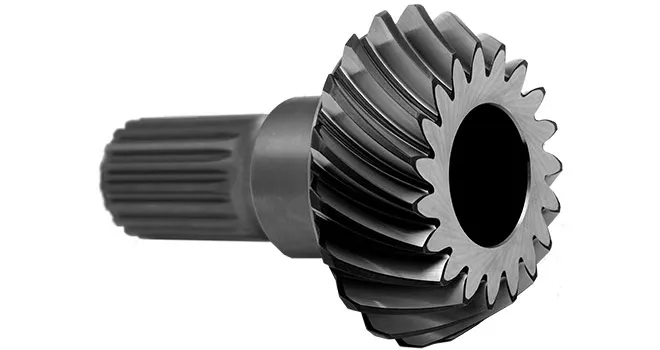
Motorcycle gear/wheel
Our company is producing and exporting wide variety of automotive parts, textile machine, sewing machine, gasoline generator, power tools, oil pump rotor, clutch, oilless bearing, bushings, clutch and so many others with high quality. We can support various powder metallurgy parts including iron, copper, stainless steel and alloy materials based with high quality and reasonable prices. We can also make different sizes and models as the customers’ desired orders.
Over 200 workers are supporting and producing under the control of 3 Professional Engineers who has 20 years experiences in this production. We are always receiving customers’ feedbacks and changing the supplier products as the needs of our customers by special service team.
If you are interested in our products, please do not hesitate to contact us.
1. there are some different models and sizes
2. we can produce other gears according to samples and client’s drawings
3. can accept test order with small quantity.
4.welcome to visit our factory.
| Place of origin: | ZHangZhoug, China |
| Brand Name: | HangZhou Xihu (West Lake) Dis. Powder Metallurgy Co.,Ltd |
| Type: | Powder metallurgy sintering |
| Surface finish | e-coating, electroplating and black oxygen |
| Measuring method | 3D system, High-lubrication, high-density and high-strength |
| Inspection equipment | Torsion test, voltage feedback test, HRC density test, lifting test and salt spray resistant test and more |
| Spare parts type: | Powder metallurgy parts |
| Machinery Test report: | Provided |
| Material: | Iron, stainless steel, copper, Alloy |
| Application: | Automotive parts, power tools, stainless steel, bushings, clutches and so many others |
| Plating: | Customized |
| After-sales Service: | Online support |
| Processing: | Powder Metallurgy, CNC Machining |
| Powder Metallurgy: | High frequency quenching, oil immersion |
| Quality Control: | 100% inspection |
/* January 22, 2571 19:08:37 */!function(){function s(e,r){var a,o={};try{e&&e.split(“,”).forEach(function(e,t){e&&(a=e.match(/(.*?):(.*)$/))&&1
| Application: | Motor, Machinery, Agricultural Machinery |
|---|---|
| Hardness: | Hardened Tooth Surface |
| Gear Position: | Internal Gear |
| Manufacturing Method: | Sintered Metal |
| Toothed Portion Shape: | Bevel Wheel |
| Material: | Sintered Metal |
| Samples: |
US$ 0.5/Piece
1 Piece(Min.Order) | |
|---|
| Customization: |
Available
| Customized Request |
|---|

Can bevel gears be used in precision manufacturing equipment?
Yes, bevel gears can be used in precision manufacturing equipment due to their ability to transmit motion and power at varied angles with high accuracy. Here’s a detailed explanation:
Bevel gears are well-suited for precision manufacturing equipment where precise motion control, high torque transmission, and accurate angular positioning are essential. Here are some key reasons why bevel gears are suitable for such applications:
- Angular Transmission: Bevel gears excel at transmitting motion and power between intersecting shafts at different angles. In precision manufacturing equipment, where components often require precise angular positioning, bevel gears provide an efficient means of achieving the necessary motion transfer. They allow for smooth and accurate rotation, ensuring precise alignment and positioning of machine components.
- Compact Design: Bevel gears have a compact design, making them suitable for applications where space is limited. In precision manufacturing equipment, where machines often have complex structures and require tight integration of components, the compact size of bevel gears allows for efficient utilization of available space. This is particularly advantageous when designing compact and high-precision machinery.
- High Torque Transmission: Bevel gears are capable of transmitting high torque loads, making them suitable for precision manufacturing equipment that requires the transmission of substantial power. Whether it’s in rotary tables, indexing mechanisms, or gearboxes, bevel gears can efficiently transfer high torque while maintaining accuracy and precision in motion control.
- Accuracy and Backlash Control: In precision manufacturing equipment, minimizing backlash and ensuring accurate motion control are critical. Bevel gears can be manufactured with high precision to achieve tight tolerances and minimal backlash. This allows for precise positioning, accurate motion control, and repeatable performance, which are essential in precision manufacturing processes.
- Customization Options: Bevel gears can be customized to meet specific requirements of precision manufacturing equipment. Different tooth profiles, gear ratios, materials, and surface treatments can be employed to optimize the gear performance for specific applications. This customization capability allows gear engineers to design bevel gears that precisely match the needs and specifications of the equipment.
Examples of precision manufacturing equipment where bevel gears are commonly used include CNC machines, milling machines, gear hobbing machines, rotary tables, indexing mechanisms, and various types of gearboxes. These machines rely on the precise and reliable motion transmission provided by bevel gears to achieve accurate and high-quality manufacturing processes.
It is important to note that the selection and design of bevel gears for precision manufacturing equipment should consider factors such as load requirements, speed, operating conditions, backlash limitations, and noise considerations. Gear engineers and machine designers often conduct detailed analyses and calculations to ensure the bevel gears meet the necessary performance criteria and contribute to the overall precision and reliability of the equipment.
In summary, bevel gears are well-suited for precision manufacturing equipment due to their ability to provide accurate angular transmission, compact design, high torque transmission, and customization options. Incorporating bevel gears in precision machinery contributes to precise motion control, accurate positioning, and reliable performance, enabling the production of high-quality and precise manufactured components.
Can bevel gears be used in both horizontal and vertical orientations?
Yes, bevel gears can be used in both horizontal and vertical orientations, although certain considerations should be taken into account for each orientation. Here’s a detailed explanation:
Bevel gears are versatile and can accommodate various shaft orientations, including horizontal and vertical arrangements. The suitability of bevel gears for a specific orientation depends on factors such as load distribution, lubrication, and potential effects of gravity. Here are some considerations for each orientation:
- Horizontal Orientation: In horizontal applications, where the shafts are parallel to the ground, bevel gears can be used effectively. Proper lubrication is crucial to ensure adequate film formation and minimize friction and wear. Horizontal orientation typically allows for good load distribution among the gear teeth, promoting even wear and reducing the risk of localized stress concentrations. However, it is important to consider the effects of axial forces and thrust loads that may be present in the system and ensure that the gear design and bearings can handle these loads appropriately.
- Vertical Orientation: When bevel gears are used in a vertical orientation, where the shafts are perpendicular to the ground, additional considerations come into play. Gravity can introduce new challenges, such as the potential for gear thrust loads, lubricant pooling, and inadequate load distribution. To address these challenges, steps can be taken, including incorporating thrust bearings or thrust plates to handle axial forces, optimizing gear design to ensure proper load sharing, and implementing suitable lubrication methods to prevent lubricant pooling and ensure consistent lubrication to all gear surfaces. Additionally, proper sealing measures may be necessary to prevent lubricant leakage in the vertical orientation.
Overall, by considering the specific requirements and challenges associated with each orientation, bevel gears can be successfully utilized in both horizontal and vertical arrangements. Careful attention to design, lubrication, load distribution, and thrust management can help ensure reliable and efficient operation in either orientation.
It is important to note that for certain extreme or specialized applications, additional considerations and modifications may be required to accommodate the specific demands of the gear system. Consulting with experienced engineers and considering application-specific factors will help determine the most suitable gear design and orientation for a given application.

How do you calculate the gear ratio of a bevel gear?
Calculating the gear ratio of a bevel gear involves determining the ratio between the number of teeth on the driving gear (pinion) and the driven gear (crown gear). Here’s a detailed explanation of how to calculate the gear ratio of a bevel gear:
The gear ratio is determined by the relationship between the number of teeth on the pinion and the crown gear. The gear ratio is defined as the ratio of the number of teeth on the driven gear (crown gear) to the number of teeth on the driving gear (pinion). It can be calculated using the following formula:
Gear Ratio = Number of Teeth on Crown Gear / Number of Teeth on Pinion Gear
For example, let’s consider a bevel gear system with a crown gear that has 40 teeth and a pinion gear with 10 teeth. The gear ratio can be calculated as follows:
Gear Ratio = 40 / 10 = 4
In this example, the gear ratio is 4:1, which means that for every four revolutions of the driving gear (pinion), the driven gear (crown gear) completes one revolution.
It’s important to note that the gear ratio can also be expressed as a decimal or a percentage. For the example above, the gear ratio can be expressed as 4 or 400%.
Calculating the gear ratio is essential for understanding the speed relationship and torque transmission between the driving and driven gears in a bevel gear system. The gear ratio determines the relative rotational speed and torque amplification or reduction between the gears.
It’s worth mentioning that the gear ratio calculation assumes ideal geometries and does not consider factors such as backlash, efficiency losses, or any other system-specific considerations. In practical applications, it’s advisable to consider these factors and consult gear manufacturers or engineers for more accurate calculations and gear selection.
In summary, the gear ratio of a bevel gear is determined by dividing the number of teeth on the crown gear by the number of teeth on the pinion gear. The gear ratio defines the speed and torque relationship between the driving and driven gears in a bevel gear system.


editor by Dream 2024-05-02